
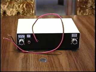
Disclaimer - This material is presented here to help others, who have never done this before, as was my situation. It is a collection of information which I obtained from many helpful people. Please do not hold me responsible for problems that you encounter as a result of reading this information
.A 222 MHz Transverter Project
Original Design by Zack Lau (W1VT), this project and supplemental notes by Rick Bandla (VE3CVG)


The original project was published in July'93 QEX magazine.
Before starting construction, collect all the parts to complete the 3 boards in the design: circuit boards, semiconductors, and surface mount parts, wire for inductors, xtal, toroid form, etc. In addition you may want to consider a case, connectors, PA, or front end switching (you may not require it, depending on the radio you use for an IF - or can be done with almost any small 12v relay). You may also need to build a 3 resistor pad to reduce the Tx RF level from your transmitter.
If you'd like to try a project with a little surface mount construction, and also join a growing group of us on 222 MHz SSB (or CW or ....) please consider building one of these xvrtrs. Parts will cost you a little over $150 (Cdn) which is roughly half of the equivalent 222 MHz xvrtr kits from major suppliers.
The usual SSB calling frequency for the 1.25M band is 222.100 MHz. Please do not ragchew on the calling frequency.
 LO Schematic
 Tx Schematic
 Rx Schematic
 Tx and Rx Board Layouts
 LO Board Layout
 Rx and Tx Board Pattern
zl222drv.zip
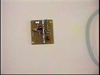
One possibility is to buy the 30w brick PA for 222MHz from DEM. Cost is about $80 US + a heat sink + case and connectors. You may also want to use a relay to bypass the amp during receive. The brick can be driven with 100 - 200mw.
There are many surplus Motorola Maxor 80 commercial 160 MHz FM transceivers around. This transceiver makes a pretty good APRS radio but because of the channel limitations and the cost of xtals, its not much good for anything else in ham radio except .......
The Maxor 80's PA module can produce 25 watts of RF, includes a hefty heat sink, a PIN diode TR switch. The amplifier module includes a M9860 driver and M9583 final.
This amp is for FM, and is a Class C RF amplifier. If it could be rebiased for Class AB, it might make a pretty good SSB amplifier. Furthermore, if it could be modified to tune up to 222 MHz, it could make a very inexpensive PA for our 222 MHz xvrtr project. So... can any of you design wizards out there, please suggest the necessary changes to bias this amplifier for SSB and CW use?
Check the article on (re-)biasing PA's for SSB by Ian G3SEK, noted columnist for RadCom, at http://www.ifwtech.co.uk/g3sek/tr-bias/tr-bias1.htm#1. Maybe someone could apply the info in the article to the Maxar80 PA for the group?
Also see G3SEK notes (from email).
To download a copy of the dwg of the PA modules click on the link below
20010527 0141K  max80paschem.zip
20010528 0173K  max80palayout.zip
20010528 0093K  max80paparts.zip
Doug (VE3XK) has suggested using the old Maxor80 case for the transverter. Good idea Doug. We will have to check it out as soon as the boards arrive.
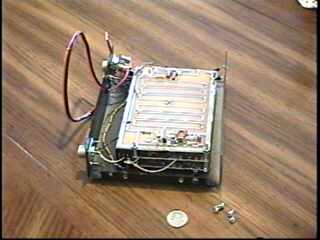
In terms of module packaging:
An FM handheld test radio and rubber duckie antenna that will Rx on 194.000 MHz and on 222.100 MHz is very helpful to assist during testing and troubleshooting your transverter.
Remember: ground ground ground - common grounds between boards - grounded coax at each end or very short leads and a ground lead near it.
I suggest that you use series 1N4004 or equiv diodes in the +12v feed at the board to protect against polarity reversals.
The first board that must be working is the LO, so get it going. Then work on the TX. I lay the LO and the Tx on a flat surface and connect the Tx to the LO using 1/2" long lead clippings from the output of the LO board to the "LO in" of the board under test. I debug it, then disconnect it, and connect the Rx in the same fashion and debug it. This approach minimizes mistakes and confusion. Trust me, it is easy to make a mistake and the result can be a disaster so be careful.
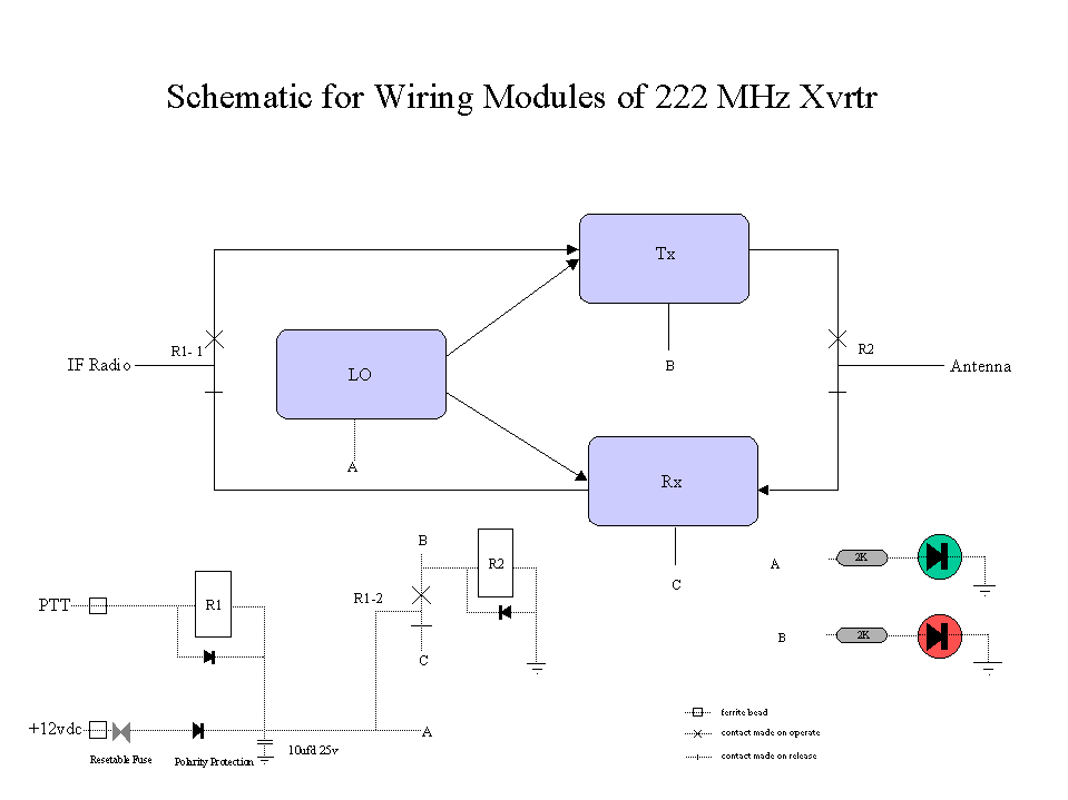
After all your boards are tested and working, you can worry about packaging, getting the IF T/R relay working, getting the antenna T/R switching working, and getting the power T/R switching working.
When working on the Local Oscillator (LO) tune the handheld test radio to 194MHz. The LO has lots of output and you should easily hear it in any radio that tunes to 194MHz. If you have a counter, and you discover that the supplied variable capacitor is too sensitive or that the xtal will not quite tune onto frequency, you might consider installing a small fixed value capacitor in parallel with the variable cap. Do not attempt to precisely set the frequency of the LO until you have the Rx board or Tx board connected, as this tends to load the LO slightly. NOTE: The LO is on all the time, it is not switched by the T/R relay.
Sometimes when you apply power, you cannot hear the LO. The variable cap may have to be adjusted to ensure that the oscillator starts easily.
I have found that the MAR3 in the stage immediately before the MAV11 final,could be replaced with a MAR6 to get better performance. This will mean that the bias for that stage will have to be adjusted and the 220 ohm 1/2w resistor should be replaced with a 620 ohm 1/4w resistor. I have found consistently better performance with the MAR6. Coincident with the preceding change I also confirmed that this xvrtr works best with about 1 mw of drive (i.e. 0 dBm). My FT817 on its lowest power setting puts out 1/2w - verified with a power meter. My pad consisted of a 51 ohm 1/2w resistor to ground on input of the pad, a 470 ohm series resistor (1/4 watt is fine) and another 51 ohm resistor to ground on the output of the pad (i.e. on the input to the Tx board). On the output of this pad I measured 1 mw, as hoped. I later replaced the 470 ohm resistor with a 1.2k for slightly better stability consistency from board to board.
In my installation, I used an FT817 as an IF radio. I set the radio for 1/2w output and constructed the RF attenuation pad right on the IF input of the TX circuit board.
If you are having problems tracking a signal through the Tx board, use the handheld tuned to 222.100MHz and the IF radio tuned to 28.100 and transmitting in FM mode. LSB and USB do not work well for this test. Move the handheld antenna (radio tuned to 222.100MHz) across the tuned circuits on the board, while listening. The antenna has to be a half inch or so from the board. You should hear the signal in the handheld, for all stages after the mixer. If you hear the signal at one point and find that at the next stage it's gone, in all probability, that stage is defective.
If you are using the MAR3 (original design) you should get 4mw output from your Tx board +/-. If you are using the MAR6, you should see about 10mw. Do not forget to re-bias the MAR6 using the 620 ohm resistor in place of the 220 ohm.
After the Tx board is working, set the LO xtal frequency as closely as possible. I can generally get it within 10Hz. If your xtal will not tune far enough, you may have to pad the variable capacitor.
When testing your Rx board, be sure that your IF radio is connected and tuned to 28.100MHz on USB or CW. Carefully apply power to the LO and Rx board. You should hear an increase in noise of the IF radio, when the LO and RX board are powered. IF you disconnect power, the noise should decrease. This is an excellent indicator that at least part of your RX board is working. You will only detect the noise if your IF radio is set for CW or USB. If you do not hear the change in noise level - start hunting.
Apply a very weak signal on 222.100MHz from an attenuated signal generator or other RF source. Never transmit into the RX board from either the IF end or the antenna end, or you will damage components. I have found that the Rx convertor sensitivity is pretty good and it receives signals below -120dBm. The noise figure is also quite acceptable.
I finally finished packaging the 222 xvrtr.
I hooked my 222MHz plumber's delight antenna to it this morning Nov.16,2001, and worked Les VE3FHU who is 7 mi south of Monkland. I'm roughing that at about 70km maybe more. Les gave me 5 x 4 and he was 5 x 9. I was using my FT817 as an IF. The xvrtr was running with NO PREAMP and NO PA ..... that's just 4mw. YES! 4mw power out.
So ...... there's a challenge for you ... Who can beat my record? NO PA REQUIRED to get on 222MHz with 4mw.
Alex (VE3KSK) kindly passed along some photos of his finished transverter modules and home made K1FO antenna. Nice work!
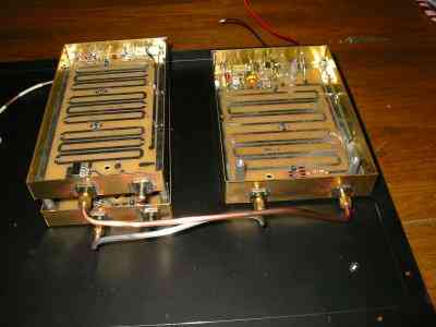


If you can help make the design changes to use the Maxor amp for 222MHz, please email me. 73. Rick (VE3CVG)
 Click here for more info on The Infernal Tower.
 Click here to view my Antenna Area and my 222MHz Plumber's Delight.
 Click here for info on my DXpedition to VY0 Land
 Click here to visit my Swap Page.
 To go to VE3CVG Home Page or
click here to send me email:
 ve3cvg@rac.ca