All round tubing elements were cut with a plumber’s tubing cutter available at most hardware stores. The aluminum boom and rod, and the teflon can be cut with a sharp hacksaw.
All aluminum that I used is T6 hardness.
I purchased my aluminum at Ridalco, 1551 Michael Street (near St.Laurent and Belfast). Total material cost was under $25 (incl tax), but I am a real shopper and we were building 4 at a time.
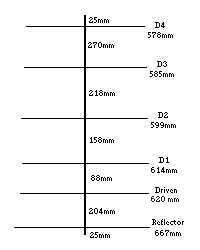
The dimensions that I used are:
Because all of the elements of this antenna, including the driven element, are fastened to the boom (metal to metal) the elements are at ground potential and tend to have a reasonable immunity to lightning damage. Also, when measuring this antenna with a simple voltmeter, you should see a very low resistance short circuit.
This antenna is short and light, and so you can choose to centre-mount it or end-mount it. You can use exactly the same boom-to-mast mounting arrangement for either mounting. If you end-mount, as I did, be sure to leave enough square boom at the reflector end. I'd suggest a little over 200mm spacing between the reflector and any mast pipe or tower leg (that way, the mast or tower acts as a 2nd reflector when positioned for vertical polarization (my theory anyway). Allowing 963mm for the boom and an additional 204mm (abt 8") plus 50mm (for mtg). Allowing for a bit of an extension to hang a counter balance on, I ended up using an overall boom length of 5 feet. You could use a bit less if you prefer. When you are intending to end mount, keep in mind that the reflector goes nearest the mast or tower, so start measuring from the director end.
I used 3/4" square tubing for the boom. A feature of 3/4" square tubing that you may find useful is that it slides just perfectly into a 1" square tube. I attached my mount directly to the boom.
Alternately you could fasten your mount to a 10" piece of 1" square tube. By sliding the 3/4" into the 1", then putting a bolt through the 2 square tubes, you end up with a handy end-mount arrangement which allows you to quickly (manually) change from horizontal to vertical polarization. Caution: Do Not Drill the 2 pieces while they are inserted one into the other, or you will never separate them. Drill the big one first, then mark the small one while inserted into the big one. Separate them, then drill the small one.
The elements are 1/2" round tubing and are fastened to the boom by attaching to 2" square plates using pop rivets..
The details of the driven element are:
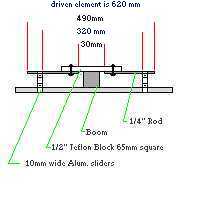
Note that all elements (driven and parasitic) fasten to the same side of the boom.
This antenna requires a balun to feed the two sides of the dipole. To make the balun, start with a piece of RG58A/U (stranded centre conductor is preferred if you can find some) which is 500mm long. On each end, remove about 1" of sheath, then either pull the centre conductor thru the exposed braid or unweave the braid. Attach an eye terminal to each end of the centre conductor. Then cut each end's braid so it is about 1/4" long. Now attach a terminal eye to each end of the braid. Be sure to solder all terminals, but be careful not to melt the insulation. You can change the length of the braid slightly to suit your antenna. The centre conductor of the balun connects between the 2 screws that hold the 2 rods. Each end of the shield is grounded to the screw that holds the insulated block to the boom. The balun and feedline extend along the boom towards the reflector end (assuming that you are end mounting).
When fastening the rods, first flatten them slightly with a hammer and anvil, then punch them and drill them very carefully.
Note that the 50 ohm coax (213) feedline centre conductor connects to either one of the screws which hold the two rods to the teflon block. The shield of the feedline is grounded to the screw that holds the insulated block to the boom. Use terminal eyes. I usually lightly crimp the terminal, then solder it with a heavy duty soldering gun or a small propane torch. If you wish, you can strengthen the connection by using sealing heat shrink tubing.
I recommend sealing all connections with liquid rubber available from electrical contractor supply houses. Its expensive but worth it.
When adjusting this antenna, you may use either an antenna analyzer (if you can find one for 222MHz), or a radio/xvrtr and a good SWR meter. You will have to experiment with the sliders on the driven element while watching the SWR. I like to use my FT-817 with my xvrtr to do this. I make several test transmissions at different frequencies while recording the SWR reading. It is important to find the resonant frequency of the antenna. After you have found the point where the SWR is best, adjust the sliders in or out, to get the best match. Now go back and confirm the resonant frequency. At this point, you may trim the driven element if the resonant frequency is too low. I ended up with my sliders exactly 320mm apart on their inside edge. Assuming you have followed these instructions, yours should be very similar.
According to my tests the antenna was centred at about 222.200 MHz and was better than 1.5:1 up to 223MHz. I have found the design to be reliably repeatable.
This antenna was used in the June 2001 VHF contest and worked very well, in spite of the fact that it was at rooftop height. The antenna was mounted on the tower mast at about the 51' mark in October 2001. It performs exceptionally well, and its hard to believe that it is only 6 elements.
Click here
 To go to Antenna Index Page
 To go to my 222 Transverter Project Page
 ve3cvg@rac.ca